
Raspberry Pi
Raspberry Pi is a microprocessor or better to say “a credit card-sized CPU”. One of the most exciting features of Pi is the GPIO. GPIO (General Purpose Input Output) pins enable us to control hardware devices or equipment like motors (DC motors, servo motors, etc), or LED. We can control a DC motor by writing simple code in Python Programming Language.
However, there are differences between DC and BO motors. A BO motor is a motor with gears inside to alter the speed or torque of the motor.
How to control the motor with Raspberry Pi
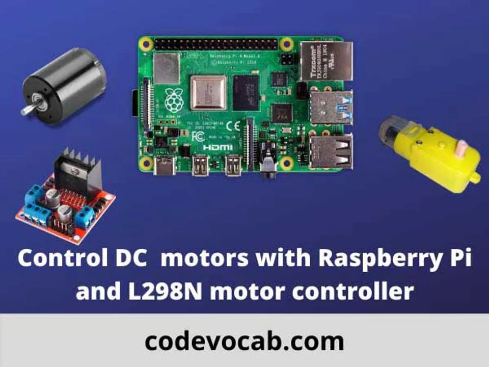
For this, we need the following things –
- A Raspberry Pi (I have used Raspberry Pi 4 Model B).
- A DC or BO motor (I have used a BO motor).
- An L298N H-bridge motor controller.
- A power supply for Raspberry pi.
- A 5 – 9 V power supply for the motor controller.
- Some male to female jumper wires.
- Some ordinary wires.
The basics –
A dc motor can be run by supplying a specific power. If we change the polarity, the motor moves in the opposite direction.
But for that, we need to manually change the wires in a normal case. In this case, we are using the L298N motor controller to control the speed and direction of the motor. The controller has four inputs and can connect two motors simultaneously. These are marked as input1, input2, input3, and input4.
GPIO pins – The GPIO pins are divided into various types including GPIO, grounds, etc. You can use either of the GPIO for your motor.
Connections –
Connect the motor to the output1. Take two male-to-male jumper wires and connect one end to the input1 and input2 of the motor controller. Connect the other end of the input1 wire to pin no GPIO 26 and the input2 wire to GPIO pin 20. Connect one end of the 9v battery to the 12v terminal of the controller. Connect the other end (the black one) to the ground (named as GND) of the motor controller. Take another female to male jumper wire. Connect the female end to pin number 6 on the GPIO header on the raspberry pi. Take another end (the male end) and connect it to the ground of the motor controller. Power up the raspberry pi with either an adaptor or a 5v power supply.
Program
import RPi.GPIO as gpio
import time
input1 = 26
input2 = 20
gpio.setmode(BCM)
gpio.setup(input1, gpio.OUT)
gpio.setup(input2, gpio.OUT)
start = time.time()
running = True
while running:
    currentTime = time.time()
    diff = currentTime - start
    if diff <= 5:
        gpio.output(input1, gpio.HIGH)
        gpio.output(input1, gpio.LOW)
    elif diff > 5 and diff <= 10:
        gpio.output(input1, gpio.LOW)
        gpio.output(input1, gpio.HIGH)
    else:
        running = False
gpio.cleanup()
Explanation of the program
The first step is to include the RPi.GPIO module, some we have done that and aliased the name as gpio. We would use all the functions of this module through the aliased name ‘gpio’.
Then, we have declared two variables named input1 and input2 and initialized them with 26 and 20 respectively. (Take a note that these are the pin numbers that we are using on the pi GPIO header as input pins).
In the next statement, we are setting the mode by which we could access the pins. We have used BCM (Broadcom SOC Channel). In this mode, we are using the pin number on the GPIO header (Not physically). For example, the 38th pin number on the header is GPIO 20. There is another mode called BOARD. In this mode, we use the pin numbers as they appear on the header. For example, if we have used the BOARD mode, and we use GPIO 38, then we are actually using pin number 38 on the header.
In the next two statements, we have defined pins 26 and 20 to act as output pins to generate the mechanical output by the motor.
The main process starts from here. We are executing a loop that lasts for 10 seconds. For the first 5 seconds, the motor would run in a particular direction, and for the next 5 seconds it would run in the opposite direction.
When input1 is HIGH and input2 is low, the motor would move in the opposite direction. We can represent HIGH with True or 1 and LOW as False or 0.
For example
gpio.output(input1, gpio.HIGH)
gpio.output(input2, gpio.LOW)
is equivalent to
gpio.output(input1, 1)
gpio.output(input2, 0)
or
gpio.output(input1, True)
gpio.output(input2, False)
When the value of variable ‘currentTime’ is greater than 10, the value of the variable ‘running’ is set to False and that is how the loop is going to terminate.
Last Words:
There are a couple of different motors and motor controllers. There are stepper motors, servo motors which can also be controlled by Raspberry Pi to make DIY (Do It Yourself) projects. To control 16 servos at a time you can use the 16 channel 12-bit PWM servo motor driver. With L298N, you can control up to two dc motors or two pairs of different DC motors.